A Tip to Judge the Condition of IGBT Module
There are some situations in the work: the damaged IGBT module should analyze the cause of the failure, or the module with good appearance should judge whether there is any abnormality. In the absence of specialized equipment, digital multimeters can be used as a common tool to help us quickly identify IGBTs. At this time, the diode file, the resistance file, and the capacitance file of the multimeter are generally used. It is worth noting that the test data of the multimeter is not universal and can only be used as a reference.
Module structure
Take the common 62mm package IGBT module as an example. The internal part is composed of IGBT (insulated gate bipolar transistor) chip, FWD (freewheeling diode) chip, bonding wire, etc. Some high current modules need to be combined by multiple sets of chips. Figure 1 is a manufacturer's 400A module:
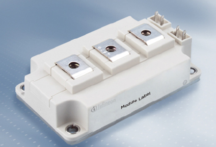
Manufacturer's 400A module
Its electrical connection is shown in Figure 3. The upper and lower bridges of the module have 4 sets of IGBT and FWD chips connected in parallel through the bonding line. The equivalent electrical symbol is shown in Figure 4:
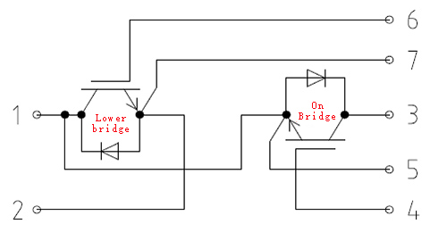
Electrical connection
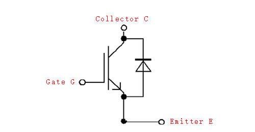
The equivalent electrical symbol
Measurement methods
1. Diode file
With the diode file, the forward voltage drop VF of the freewheeling diode can be measured. Short the gate-emitter, connect the emitter with the multimeter red pen, the black pen is connected to the collector, and the normal module VF will be around 0.3~0.7V. If the VF is too large, the FWD chip or bonding wire will be disconnected. A short circuit occurs in the FWD or IGBT chip.
The size of VF is related to the forward current IF. As shown in the figure below, there are some differences in the resistance and voltage in the test circuit of different multimeters, which will result in the difference of measurement results. Therefore, this test value cannot be compared with other multimeter test values. It can't represent the data in the data sheet. This test value has no other meaning. It can only be used to determine whether the FWD chip is good or bad.
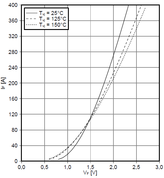
VF control
2. Resistance file
(1) Measure the resistance between the collector and emitter of each IGBT tube in the module, short the gate-emitter, the multimeter's red pen is connected to the collector, the black meter is connected to the emitter, and the normal module resistance value is generally above the megaohm level.
(2) Measure the resistance between the gate-emitter (gate-collector) of each IGBT tube in the module. The multimeter red and black test leads are connected to the gate and emitter (gate and collector) respectively, and the normal module also shows high impedance. When a driver board is connected to the module, the gate-emitter resistance is equal to the bleeder resistance, typically several thousand ohms.
Due to the measurement range of the multimeter, some of the multimeters cannot display valid values for the above high resistance measurements. Of course, when the test value is high impedance, it does not completely represent that the module is normal. The above operation method has a certain effect on the determination of the failed module, but the success rate is not very high, and the capacitance measurement result is also required.
3. Capacitor file
The multimeter measurement gear is adjusted to the capacitor file, the red pen is connected to the gate, the black pen is connected to the emitter, and the internal capacitance between the gate and the emitter of the IGBT in the module is measured, the measurement data is recorded, and then the test pen is replaced, that is, black. The meter pen is connected to the gate, the red pen is connected to the emitter, and the measured data is recorded. The capacitance of the module varies from a few nF to several tens of nF. Finally, the data is compared with other IGBT chips in the module measured by the multimeter or the measurement data of the same manufacturer and the same type of module, and the values should be the same or similar.
It is only recommended to measure the capacitance between the gate and the emitter during measurement. The Cies in the IGBT chip is the largest, Cres and Coes are much smaller than Cies, see Figures 6 and 7, and the accuracy of the multimeter for capacitance testing is limited.
In addition:
(1) Similar to the forward voltage drop VF, the test value here is different from the test value test conditions in the data sheet and can only be used as a comparison reference.
(2) If the driver board is connected to the module, it will affect the capacitance measurement result and should be removed first.
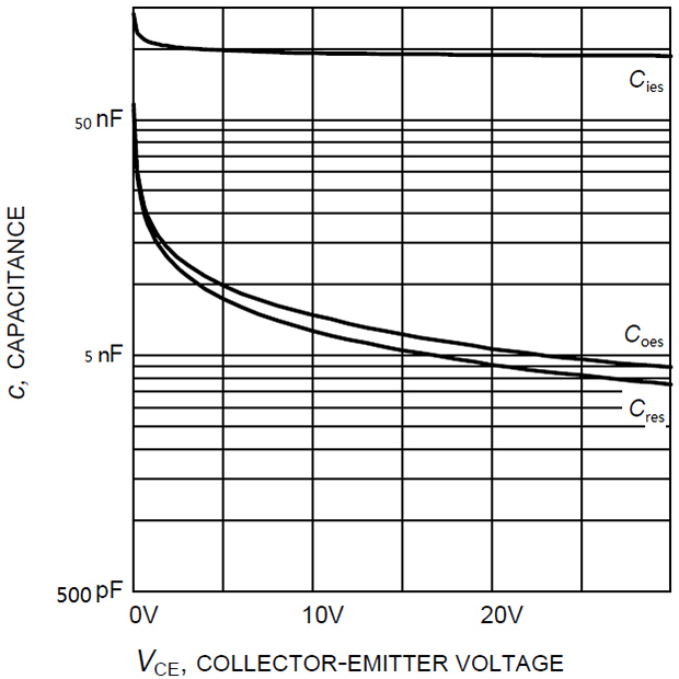
The accuracy of the multimeter for capacitance testing is limited
Summary
The simple summary of the digital multimeter to determine the IGBT quality is as follows:
|
Step |
Gear position |
Show result |
Discriminant result |
|
1 |
Diode file |
FWD pressure drop 0.3~0.7V |
FWD chip is normal |
|
The pressure drop is too small |
FWD chip or IGBT chip short circuit |
||
|
Pressure drop too large |
FWD chip break, or bond line break |
||
|
2 |
Resistance file |
Rce, Rge, Rgc high resistance state |
CE, GE, GC are not shorted |
|
Rce, Rge, Rgc low resistance state |
CE, GE, GC breakdown or short circuit |
||
|
3 |
Capacitor file |
Cies value is a few nF to tens of nF |
Normal door |
|
No value or contrast deviation |
Door breakdown or disconnection |
Note:
1. The above method is used as a preliminary discriminating method, and more accurate analysis requires special instruments.
2. Do not touch the module electrodes during the measurement process to avoid electrostatic damage or interfere with further analysis of the failed module.
 Global - English
 Spanish - Español
 French - Français
 Russian - Pусский язык
 Chinese - 中文
 Korean - 한국어
 Vietnamese - Tiếng Việt