Tension Winding in Film Printing Equipment
Introduction
- Introduction
- Related Products
- Related Solutions
- Other Related Cases
- Additional Information
- Contact us
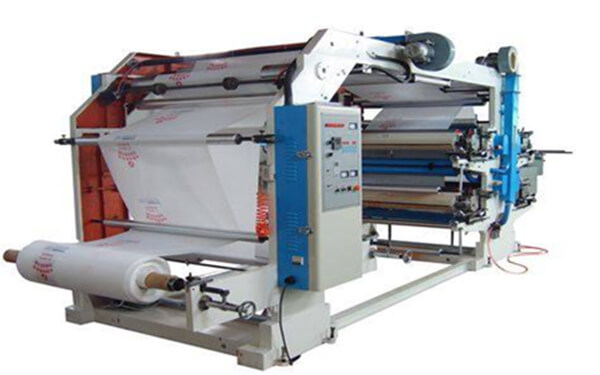
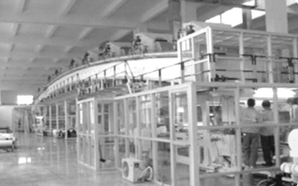
1.Plastic bags and plastic films are the major products of this customer. There are 120 sets of production lines in this factory where torque control motors are used for winding and inverters are used for pulling. The power of the torque control motor in each production line is different in accordance with different requirements. And the requirements of AC motor are used in winding as below:
(1) Reduce the maintenance costs of torque motor: the customer’s equipments run for 24 hours, leading to the high cost of time investing in the maintenance and overhaul.
(2) Reduce the workload of workers: some of the production lines need manual adjustment for the torque motor, and workers always need to pay close attention to the winding situation, which is not only very troublesome, but also causes poor forming effect .
(3) Replace the tension controller on site: some of the production lines use torque motor and tension controller at the same time. The tension controller increases the output torque of the motor by counting. But in this way, it is difficult to ensure the constant tension control and workers need to reset the volume diameter when changing rollers. The customer also gives feedback that the winding form is not very good.
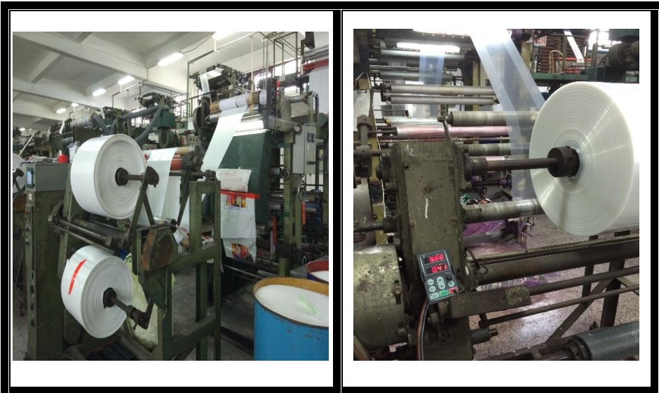
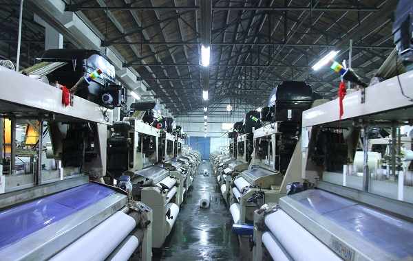
Equipment Photos On Site

Production Line Transformation Diagram
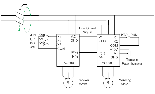
Wiring Diagram
Debugging Process
1. Inverter carries on rotary self-study function to the motor without load (very important step);
2. Require the highest line speed corresponding to the highest frequency of pulling in the front side of winding from the factory;
3. Require the mechanical DEC ratio in the winding side from factory;
4. Test the initial volume diameter;
5. Require the largest volume diameter when winding;
6. The formula may be used when debugging:
TN: Motor torque;
D: Current roller diameter;
F: Tension;
F0: Setting Tension;
D0: Initial diameter;
D1: Tape compensation modify.
Specification:
Step 1 allows the inverter to obtain accurate motor parameters in order to get accurately control;
Step 2,3,4 and 5 aim to provide accurate data to inverters when calculating volume diameter, and are the keys to realize constant tension control in the winding process.
The formula 1 and 2 in step 6 can be used to calculate the initial torque and judge whether the motor is right or not. Formula 3 is used to control the winding taper and is also very important for winding forming.
Parameters Setting
| Function Code | Function Name | Recommended Value |
| F0.00 | Control Mode | 0 |
| F0.02 | Running Command Channel | 1 |
| F0.14 | ACC Time 1 | 0.5 |
| F0.15 | DEC Time 1 | 1 |
| F2.00 | Multi-function Terminal X1 | 1 |
| F2.01 | Multi-function Terminal X2 | 56 |
| F3.11 | As Lower Limit Corresponded Setting | 8 |
| F7.00 | Speed/Torque Control Mode | 1 |
| F7.01 | Torque Given Source Selection | 9 |
| F7.10/F7.11 | Frequency Limit Selection | 0 |
| F7.12 | FWD Frequency Limitation | 100% |
| F7.13 | REV Frequency Limitation | 100% |
| F7.16 | Tension Given Source | 0003 |
| F7.17 | Tension Number Given | Based On Site |
| F7.20 | Mechanical Transmission Ratio | Based On Site |
| F7.24 | Roller Diameter Calculation Method | 0010 |
| F7.26 | Roller Diameter | Based On Site |
| F7.29 | Cut-off Frequency When Roller Diameter Calculated | 5 |
| F7.31 | Line Speed Input Source | 2 |
| F7.32 | Maximum Line Speed | Based On Site |
| F7.33 | Lowest Line Speed When Roller Diameter Calculated | Based On Site |
 Global - English
 Spanish - Español
 French - Français
 Russian - Pусский язык
 Chinese - 中文
 Korean - 한국어
 Vietnamese - Tiếng Việt

 Leave a Message