- Home
- Industry News
- Application of VEICHI inverters on wire drawing machines
Foreword
The wire drawing machine is also called a pull drawing machine. Wire drawing machine is a widely used mechanical equipment used in industrial applications, it is used in machinery manufacturing, metal processing, petrochemical, and plastic, bamboo and wood products, wire and cable and other industries.
According to its use, the wire drawing machine can be divided into metal wire drawing machine (for pre-processing of metal products such as standard parts), plastic wire drawing machine (used in the plastic products industry to produce various hollow, solid or flat yarns for deep processing of polyester, nylon, polyethylene, polypropylene, polyester chips, etc.), bamboo and wood wire drawing machine (used in the bamboo and wood products industry to make chopsticks, toothpicks, barbecue sticks, etc., pull out bamboo silk, special equipment for reprocessing of wood wool).
The wire drawing machine can be divided into a straight-through type and a water tank type by means of stretching. The wire diameter can be divided into a large drawing machine, a middle drawing machine, a fine drawing machine and a micro-drawing machine, etc. They are composed of two parts: the wire drawing and the wire. In order to improve the output, quality and cost of the cable, the wire drawing machine is generally changed to double-conversion or multi-conversion constant-tension control. At present, most of the variable-frequency synchronous control generally adopts the control mode of the external PID controller. The disadvantages of this method are as follows: The PID controller's control parameters are difficult to debug, expensive, and easy to damage. The analog quantity has attenuation and drift problems during transmission. The maintenance and maintenance costs are high. The use of the wire drawing machine inverter is easy to operate, easy to debug, and economical. It is a trend in the use of wire drawing machines. At present, the wire drawing machine of VEICHI is sold well all over the country, and its reputation is very good. It has won unanimous praise from various manufacturers in the field of wire drawing machines.
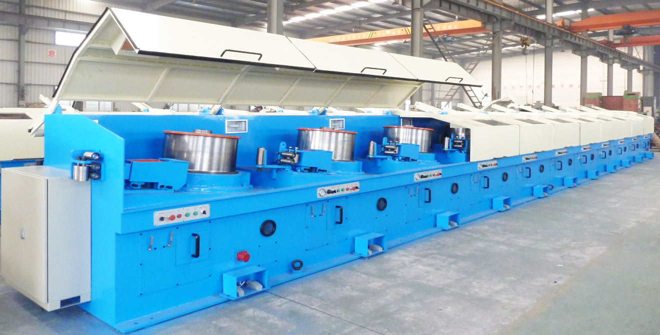
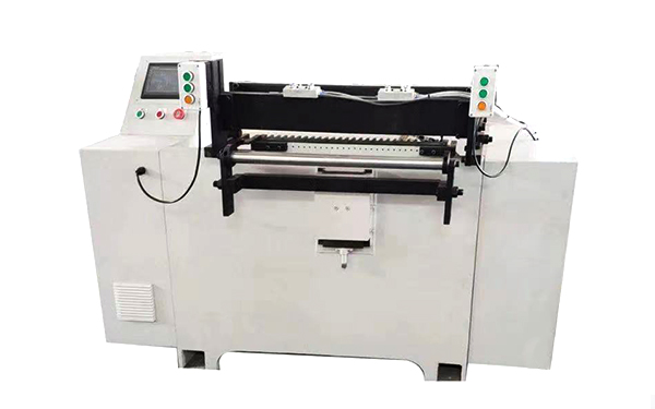
Wire drawing machine
Introduction and working principle of wire drawing machine
Introduction of straight wire drawing machine
The straight-through wire drawing machine is a small continuous production equipment consisting of a plurality of drawing heads. By drawing one by one, the wire can be cold-drawn to the required specifications at one time, so the working efficiency is relatively high. However, since the wire diameter of the wire changes after each stage of drawing, the working line speed of each drawing head should also be changed. Features: multiple plucking heads, multiple frequency conversion, multiple PID adjustment.
The principle of straight wire drawing machine
(1) The working principle of the straight wire drawing machine is to control the metal flow time of each reel to be equal.
(2) The wear of the wire drawing die, the fluctuation of the motor speed, the unevenness of the wire thickness and the like are detected by the displacement sensor, and the PID algorithm is used as the speed compensation.
(3) The speed of the last reel is given as the main, and the other reels are given by the reduction ratio and the transmission ratio.
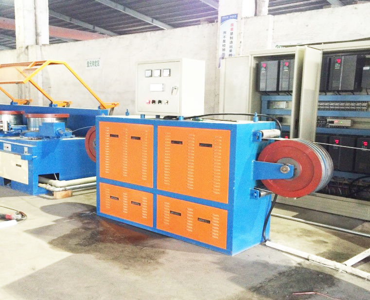
The principle of straight wire drawing machine
Introduction to the water tank type wire drawing machine
The water tank drawing machine is also called wet drawing machine, and the drawing process is carried out in the water tank, which can effectively dissipate the heat generated by the steel wire drawing and the sliding of the steel wire on the reel, and is suitable for the production of small-sized steel wire.
The working principle of the water tank type wire drawing machine
(1) The host drags the tower wheel and enters the small mouth through the large mouth of the mold to complete the process of thickening the thin line.
(2) The tension is converted into a 0-10V electrical signal by a potentiometer connected to the tension rod.
(3) The winding frequency conversion self-winding diameter calculation function, that is, as the wire is more and more, the wire speed is automatically reduced, and the tension feedback voltage is combined with the PID operation to keep the wire tension constant.
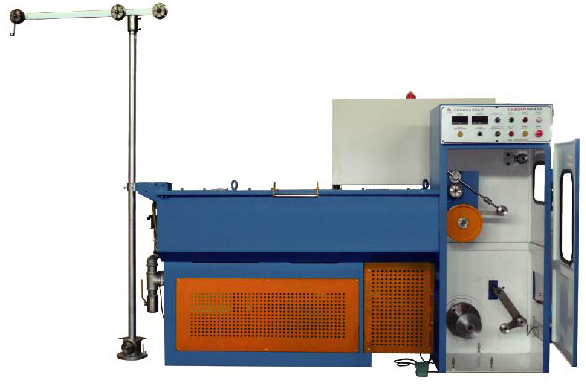
The working principle of the water tank type wire drawing machine
Process requirements for wire drawing machine inverter
(1) Superior low frequency torque, fast dynamic response, ultra-stable steady-state accuracy, and no chattering.
(2) All tension control algorithms are integrated into the inverter, and the characteristic functions of the wire drawing machine are integrated into the inverter. The complete control function of the complicated wire drawing machine can be realized without the need of peripheral control circuits.
(3) When the host starts and stops, the disconnection is never allowed. If there is a disconnection fault, it should be quickly alarmed and emergency stop.
(4) The operation is stable. During normal operation, the pendulum bar is not allowed to collide with the upper and lower limits, and the same flow rate can be maintained at the same time.
(5) Keep the line in sync during the stop, and maintain the proportional relationship of the speed of each line at all times.
(6) The inverter integrates multiple sets of special parameters of the wire drawing machine and directly calls the corresponding parameters, without the need for the customer to set the parameters one by one.
The features of AC310, AC200-L wire drawing machine inverter
(1) Unique automatic calculation of roll diameter coefficient
As the winding diameter of the take-up machine continues to increase, the output frequency of the take-up machine needs to be continuously reduced. The AC310 and AC200-L series inverters are specially equipped with a winding diameter calculation function to dynamically, real-time and automatically calculate the current winding diameter of the wire take-up machine to achieve the best constant tension take-up effect.
(2) Roll diameter coefficient K1 increment
During the running process, when the tension balance bar is off center, the automatic calculation function of the winding diameter coefficient K1 is turned on. In order to ensure the tension stability at high, medium and low speeds, the different position deviations of the pendulum rods correspond to different roll diameter coefficients K1 increments, and the different system roll diameter change rates are different. The K1 increment is adjusted to achieve accurate calculation of the roll diameter.
(3) Powerful coil diameter calculation method
In order to ensure the smooth running of the wire take-up machine near the center of the pendulum, the automatic calculation of the winding diameter is an important function. There are two automatic calculation methods for the winding diameter in AC310 and AC200-L: linear velocity method and thickness integral method. This ensures that the performance of the tension control is more perfect.
(4) Roll diameter reset (manual / automatic)
At the same line speed, the output frequency of the take-up machine at full diameter and empty diameter differs greatly. In order to synchronize the speed of the wire take-up machine and the host line, the wire take-up machine needs to perform the roll diameter reset when changing the roll. When the roll diameter automatic reset function is used, the roll diameter coefficient K1 is automatically reset after each stop. When power failure or emergency stop, the manual coil diameter reset function should be used, that is, the external multi-function terminal is defined as the coil diameter reset terminal.
(5) Friction compensation
The built-in static friction compensation and sliding friction compensation module ensure the work of overcoming the friction and make the system more perfect.
Recommended wiring method
The following wiring methods are based on AC200-L.
(1) The jog switch is connected to the X3 terminal of the main unit (factory value is jog forward)
(2) The external terminal start switch is connected to the host X1.
(3) The pull speed potentiometer is connected to +10V, VS1 and GND of the wire drawing machine (main unit).
(4) The analog output of the host AO1 terminal and GND terminal are connected to the VS terminal and GND terminal of the wire take-up machine.
(5) Short the jumper terminal J2 on the control board.
(6) The potentiometer of the tension rod is connected to the +10V, AI and GND terminals of the AC200-L series inverter.
After the feedback value of the tension balance bar is connected with the AC200-L series wire drawing machine inverter as shown above, the tension bar is moved in the direction of the tension bar swing according to the wire take-up, and the PID feedback signal (C-09) is monitored. The value should be from small to large, generally from 0.0% to 100.0%. If it is not within this range, the position of the tension potentiometer should be changed so that the center point is about 50.0%, and the tension potentiometer should be a 360° high-precision potentiometer; if the electrical adjustment is troublesome, the tension rod can be lifted directly to the physical intermediate height position guaranteed by the tension of the wire is adjusted, and then the potentiometer feedback value is 50.0%. This setting method is designed to ensure that the positive and negative deviations of the tension can be obtained by the tension bar to obtain the offset storage energy of the same position distance.
Wire drawing machine recommended parameters (AC200-L)
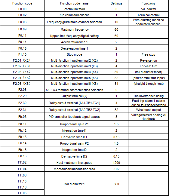
Wire drawing machine recommended parameters (AC200-L)
Water tank type double frequency conversion host (wire drawing machine) recommended parameters
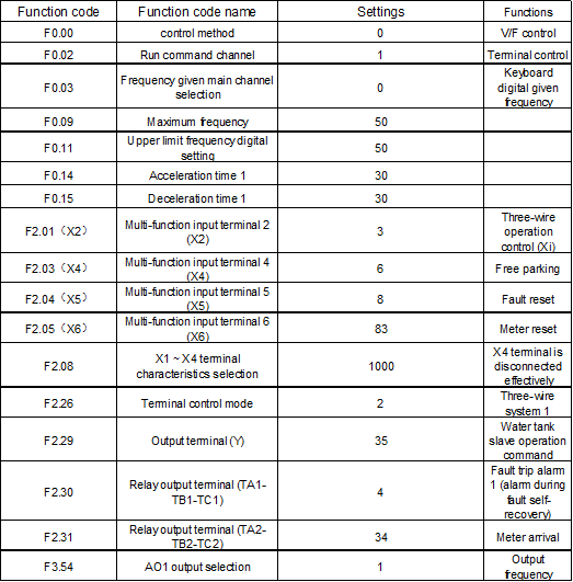
Water tank type double frequency conversion host (wire drawing machine) recommended parameters
Water tank type double frequency conversion wire machine recommended parameters
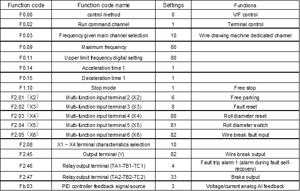
Water tank type double frequency conversion wire machine recommended parameters
Note: The above recommended parameter values may not be applicable to certain special conditions and will be adjusted according to site conditions during use.
Inverter debugging
Main unit, wire take-up machine wiring
The output frequency of the host inverter is connected by the programmable analog output port A01 and GND terminal to the current input port AS and GND of the line-receiving inverter; the output frequency of the host inverter is used as the feed-forward frequency of the wire take-up machine, and the wire take-up machine The internally calculated PID adjustments work together to ensure that the tension of the retractable line is constant.
Wire take-up feedback wiring
The three ends of the tension balance lever potentiometer are connected to the +10V, AI, and GND of the take-up inverter, and are set according to the maximum position feedback voltage and the lowest position feedback voltage of the swing lever [F3.06] and [F3.08], respectively. It can guarantee that the PID feedback value is 50% when the pendulum is in the middle position. The tension feedback potentiometer should be a 360° high precision potentiometer.
Brake resistor wiring
In order to ensure the tension of the retracting line is constant, the inverter of the take-up machine needs to accelerate and decelerate in a short time. When the speed is decelerated, the linear voltage of the inverter will rise. To ensure the normal operation of the inverter, an external brake is required. For the resistance and braking resistance, refer to the AC200 Series Inverter User Manual. The braking resistor is connected to the (+) and PB of the AC200-L series wire drawing machine.
Wire break detection function
When the tension feedback value is less than the PID disconnection detection lower limit [FF.20] or exceeds the PID disconnection detection upper limit [FF.21] and continues for the time set by [FF.24], the inverter is [FF. 25] The method of selection is handled accordingly. Broken wire alarm lower limit [FF.20]: Set the lower limit of the wire drawing machine PID disconnection detection, the feedback signal is less than the disconnection alarm lower limit value and continue [FF.24] disconnection detection judgment delay, then it is considered as drawing The machine is disconnected. Broken line alarm upper limit [FF.21]: Set the upper limit of the wire drawing detection of the wire drawing machine. The feedback signal exceeds the upper limit of the wire break alarm and continues [FF.24] After the wire break detection judgment delay, it is considered that the wire drawing The machine is disconnected. Wire break detection judgment delay [FF.24]: In order to avoid false alarms.
When the system detects a disconnection, after the disconnection detection determines the delay time, it will report the disconnection fault. Disconnection fault operation mode: 0, free stop and alarm; 1, only the disconnection fault terminal action, when the inverter detects the disconnection, continue to run. At the same time, if the multi-function output terminal is set to the disconnection output, the valid signal is output immediately.
In order to avoid false alarm during startup or shutdown, the inverter can be set to run longer than [FF.22] and the inverter output frequency is higher than the [FF.23] setting frequency.
The disconnection is detected and the inverter is free to stop and report an "E.PID" fault. If [FF.25] is set to 1, the disconnection fault is automatically reset after the [FF.27] set time.
Brake control
When the slave stops, the brake signal is output (output from the selected output terminal), and the output is stopped immediately after the time set by [FF.29]. During the brake signal output, if the run command is valid, stop the brake immediately.
 Global - English
 Spanish - Español
 French - Français
 Russian - Pусский язык
 Chinese - 中文
 Korean - 한국어
 Vietnamese - Tiếng Việt


 Leave a Message