Application of VEICHI inverter in high-speed spindle motor
Introduction
- Introduction
- Related Products
- Related Solutions
- Other Related Cases
- Additional Information
- Contact us
Overview
High-speed electric spindles have appeared in the field of CNC machine tools in recent years, and are a new technology that integrates machine tool spindles and spindle high-speed motors. The main drive system of the high-speed CNC machine tool cancels the pulley drive and gear drive and is directly driven by the built-in high-speed motor, thereby shortening the length of the main drive chain to zero, realizing the "zero transmission" of the machine tool.
With the maturity of technology, the application of this transmission method is quite common, and it is widely used in industrial equipment such as CNC engraving machines and confidential grinders. The drive technology of high-speed motors also needs to be improved. VEICHI AC310/AC300/AC10 series inverters are at the forefront of the industry with unique DSP algorithms for driving high-speed motors. In the following two industries, cutting machines (woodworking machinery) and polishing machines, we will introduce the application of VEICHI inverters in high-speed spindle motors.
System introduction and process requirements
(1) CNC cutting machine
The CNC cutting machine is an auxiliary processing automatic woodworking machine. It can cut, milling, beveling, perforating, carving, etc. of various panel furniture such as wardrobe cabinets, cabinet cabinets, computer desks, panel furniture, office furniture, wooden speakers, wooden kitchen utensils, etc. Because the equipment has high processing efficiency, high processing accuracy, simple operation, and can be customized with furniture design systems to achieve different needs, it is widely used in the furniture industry.
The system is composed of a controller, servo, (frequency converter) spindle, bed, and so on. The special software of the controller performs design, programming, and reading of drawings, and transmits them to the servo. The material is processed according to the generated XYZ three-axis cutting and engraving path, and the designed plane, graphics, and text can be engraved. It can replace traditional sliding table saws and electronic cutting saws, cutting materials, and vertical holes in one go, to quickly process cutting materials and processing special shapes. The operation principle of the equipment is as follows:
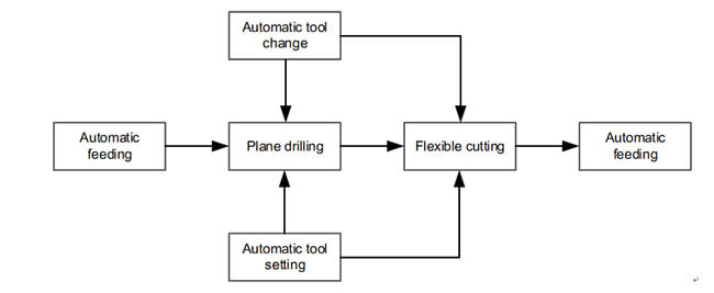
Figure 2-1 Operation principle of cutting machine equipment
System performance requirements:
1. The inverter runs smoothly, with low noise and high overload capacity;
2. Acceleration and deceleration time 2s-3s, no overcurrent and overvoltage faults;
3. Acceleration and deceleration start smoothly without jitter;
4. High-speed electronic spindle motor power 9kW, maximum frequency 800Hz, maximum speed 24000rpm;
5. Scheme selection: AC310-T3-011G/015P-B
(2) Light guide plate polishing machine
The light guide plate polishing machine is a precision grinding and polishing equipment, which places the ground and polished material on the grinding jig and fixes it, and the spindle motor rotates counterclockwise at high speed. Through the front and back, up and down movement and the workpiece on the fixture for relative running friction, to achieve the purpose of grinding and polishing. The operation principle diagram of the equipment is as follows:
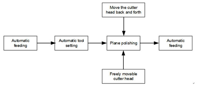
Figure 2-2 Operation principle of light guide plate polishing machine
System performance requirements:
1. The inverter runs smoothly, with low noise and high overload capacity;
2. Acceleration and deceleration time 1s-3s, no over-current and over-voltage faults;
3. Acceleration and deceleration start smoothly without jitter
4. High-speed electronic spindle motor power 1.8kW, rated frequency 1000Hz, rated speed 60000rpm;
5. Scheme selection: AC10-T/S2-1R5G-B
Electrical schematic diagram
(1) AC310 is used on CNC cutting machine
a) System architecture diagram
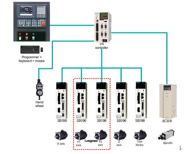
Figure 3-1 Schematic diagram of system architecture
1. Simple operation, rich functions: simple parameter setting, intuitive operation, easy to respond to changes in market demand.
2. With high-performance products: The system is equipped with an SD700 AC Servo System + AC310 series vector inverter. High precision, fast response, good rigidity, strong anti-interference ability, high reliability, long service life, high efficiency, and low temperature, strong overload capacity, large starting torque, good static rigidity, etc.
3. Multiple control and convenient communication: SD700 AC servo system and AC310 series vector inverter support pulse control, EtherCAT, DP and CAN bus communication control.
b) Inverter wiring diagram
1. External X terminal controls start and stop;
2. AI speed regulation and internal digital setting (400Hz-800Hz, 12000rpm-24000rpm);
3. Speed regulation can be switched at will;
4. External braking resistor realizes 1s-3s fast acceleration and deceleration;
5. The fault output is fed back to the upper computer to achieve multiple protections.
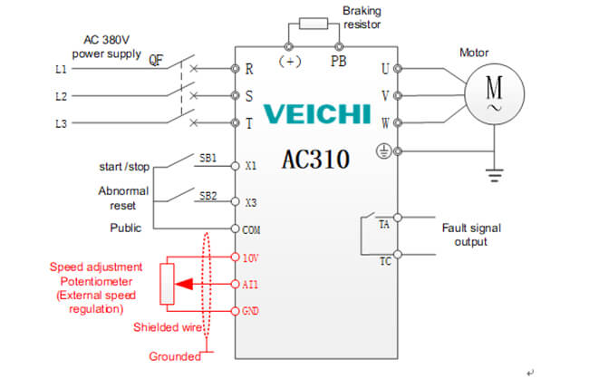
Figure 3-2 Electrical wiring schematic diagram of AC310 series inverter
(2) AC10 is used in polishing machine
a) System architecture diagram
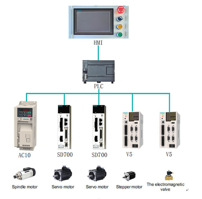
Figure 3-3 Schematic diagram of system architecture
1. The system has fast response, high precision and strong overload capacity, which greatly improves production quality and efficiency;
2. A variety of communication methods to meet the multi-faceted needs of customers;
3. The narrow book design of AC10 series inverters provides various installation methods and saves space.
b) Inverter wiring diagram
1. External X terminal controls start and stop;
2. Internal digital setting (1000Hz 60000rpm) speed regulation;
3. External braking resistor realizes 1s-2s rapid acceleration and deceleration;
4. The fault output is fed back to the upper computer to achieve multiple protection
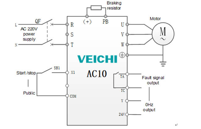
Figure 3-4 Wiring diagram of AC10 series inverter
Parameter setting
(1) Parameter setting of AC310 series inverter cutting machine
| Function code | Name | Parameter value | Description |
| F01.01 | Run command channel | 1 | Terminal control |
| F01.02 | Frequency given source channel A | 0 | Keyboard number given (use AI1 as 2) |
| F01.14 | Frequency command resolution | 1 | Set to 1 as a decimal |
| F01.10 | Maximum frequency | 800Hz | Set according to actual needs on site |
| F01.12 | Digital setting of upper limit frequency | 800Hz | Set according to actual needs on site |
| F01.09 | Keyboard number given frequency | 600Hz | Set according to actual needs on site |
| F01.22 | Acceleration time | 3s | Set according to actual needs on site |
| F01.23 | Deceleration time | 2s | Set according to actual needs on site |
| F01.40 | Carrier frequency | 5kHz | Carrier frequency setting 5kHz |
| F01.41 | PWM control mode | 0111 | PWM modulation mode two-phase three-phase automatic switching |
| F02.02 | Motor rated power | 9 | Set according to the motor nameplate |
| F02.03 | Motor rated frequency | 400Hz | Set according to the motor nameplate |
| F02.04 | Motor rated speed | 12000rpm | Set according to the motor nameplate |
| F07.22 | DC braking start frequency | 1Hz | Set to 1Hz |
| F07.24 | Stop DC braking time | 0.5s | DC braking time 0.5s |
| F10.14 | Dynamic braking enable | 1 | Turn on dynamic braking |
| F06.22 | Relay T output | 4 | Fault alarm output (default is OK) |
(2) Parameter setting of AC10 series inverter polishing machine
| Function code | Name | Parameter value | Description |
| F01.01 | Run command channel | 1 | Terminal control |
| F01.09 | Keyboard number setting frequency | 1000Hz | Operating frequency is 1000Hz |
| F01.10 | Maximum frequency | 1000Hz | The maximum frequency is set to 1000 Hz |
| F01.12 | Upper limit frequency | 1000Hz | The upper limit frequency is set to 1000 Hz |
| F01.22 | Acceleration time 1 | 1.5s | Acceleration time 1 is 1.5s (Delta set 6s) |
| F01.23 | Deceleration time 1 | 1.5s | Deceleration time 1 is 1.5s (Delta sets 6s) |
| F01.40 | Carrier frequency | 5.5KHz | Carrier frequency is set to 5.5KHz |
| F02.01 | Motor pole number | 2 | Set to 2P according to the motor nameplate |
| F02.02 | Motor rated power | 1.8Kw | Set as 1.8Kw according to the motor nameplate |
| F02.03 | Motor rated frequency | 1000Hz | Set to 1000Hz according to the motor nameplate |
| F02.04 | Motor rated speed | 60000rpm | Set to 60000rpm according to the motor nameplate |
| F02.06 | Motor rated current | 5A | Set to 5A according to the motor nameplate |
| F06.21 | Output Y terminal | 14 | Set as lower limit frequency arrival |
| F06.22 | Relay output | 4 | Set as fault alarm |
| F10.00 | Overcurrent suppression function | 1 | Acceleration and deceleration are valid, constant speed is invalid |
| F10.11 | Bus overvoltage suppression function | 0010 | Turn off overvoltage suppression |
| F10.14 | Dynamic braking enable | 1 | Turn on but turn off overvoltage suppression |
Control advantages
1.AC310/AC300/AC10 series inverter has a wide range of speed regulation: V/F mode speed control range 0-2000Hz, vector mode speed control range 0-1500Hz.
2. High speed stabilization accuracy: ≤0.5% of rated synchronous speed (asynchronous) in open-loop control mode, higher synchronous motor;
3. Equipped with Soft-PWM function to realize low noise and low interference operation.
4. High overload capacity: greatly increase the overload capacity to 150% 60s, 200% 0.5s;
5. Software and hardware-style protection circuit design can quickly perform ground short-circuit and output short-circuit protection;
6. The whole series supports built-in RFI filter, which can effectively suppress electromagnetic interference greatly;
7. Isolation air duct design: The air duct is sealed to isolate the heat dissipation system from the electronic parts, so that wood chips and dust will not be forced into the body through the fan.
Field application diagram
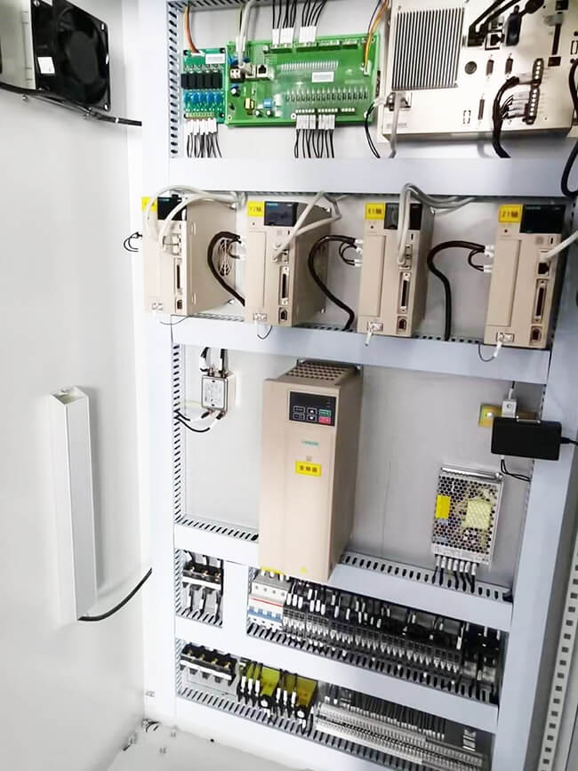
Figure 6-1 Field application diagram of AC310 woodworking cutting machine
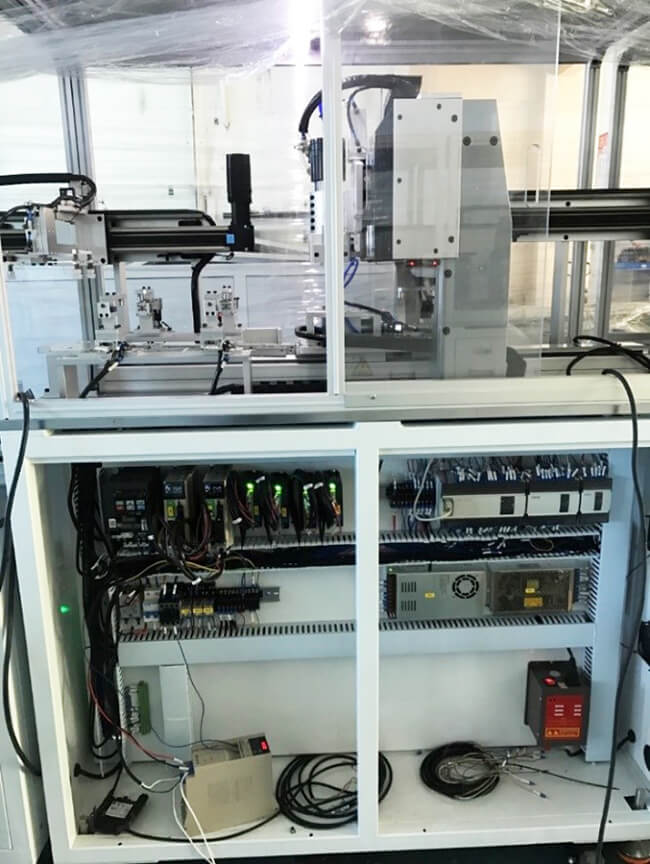
Figure 6-2 Field application of AC10 polishing machine (replace MS300)
 Global - English
 Spanish - Español
 French - Français
 Russian - Pусский язык
 Chinese - 中文
 Korean - 한국어
 Vietnamese - Tiếng Việt

 Leave a Message